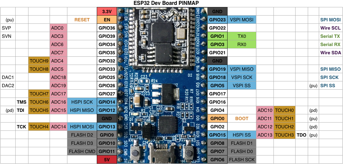
With I2C communication, each slave on the bus has its own address, a hexadecimal number that allows the ESP32 to communicate with each device. Recommended reading: ESP32 GPIO Reference Guide Scan I2C Address with ESP32 When using the ESP32 with Arduino IDE, the default I2C pins are GPIO 22 (SCL) and GPIO 21 (SDA) but you can configure your code to use any other pins. So, usually, when you’re dealing with this type of electronics components you don’t need to worry about this.Ĭonnecting an I2C device to an ESP32 is normally as simple as connecting GND to GND, SDA to SDA, SCL to SCL and a positive power supply to a peripheral, usually 3.3V (but it depends on the module you’re using).

Most sensors we use in our projects are breakout boards that already have the resistors built-in. Typical values are 4.7k Ohm for 5V devices and 2.4k Ohm for 3.3V devices. The SDA and SCL lines are active low, so they should be pulled up with resistors. Note: in many breakout boards, the SDA line may also be labeled as SDI and the SCL line as SCK. One is used for the clock signal ( SCL) and the other is used to send and receive data ( SDA). I2C communication protocol uses two wires to share information. Users can program command registers to control I☬ interfaces, so that they have more flexibility

The ESP32 supports I2C communication through its two I2C bus interfaces that can serve as I2C master or slave, depending on the user’s configuration. We have several tutorials with the ESP32 interfacing with I2C devices: In these cases, the ESP32 is the master chip and the external devices are the slaves. We use this protocol many times with the ESP32 to communicate with external devices like sensors and displays.

Follow the next tutorial to install the ESP32 on the Arduino IDE, if you haven’t already. We’ll program the ESP32 using Arduino IDE, so before proceeding with this tutorial you should have the ESP32 add-on installed in your Arduino IDE.


 0 kommentar(er)
